

No products in the basket.


Converters
PWM to Voltage Converter Module – 0–100% PWM to 0–10V
✓ In stock
The PWM to Voltage Converter translates a PWM input with a 0–100% duty cycle into a corresponding 0–10V analog output. It connects compatible PWM-generating controllers to equipment requiring a voltage control signal. Confirm the module’s supply voltage, PWM frequency range, input logic level, and output load requirements before use.
₨ 700
PWM to Voltage Converter for Analog Control
The PWM to Voltage Converter provides an interface between a PWM signal source and equipment that accepts a 0–10V analog control input. Its listed conversion range maps 0–100% PWM duty cycle to a corresponding output voltage.
For students, automation technicians, and electronics developers in Pakistan, this module offers a way to connect compatible digital control projects with analog-input equipment.
Convert Duty Cycle into Voltage
PWM controls the proportion of time a signal stays high during each cycle. This converter translates that duty cycle into a voltage level.
With an ideal linear 0–10V conversion, 0% duty cycle corresponds to 0V, 50% corresponds to 5V, and 100% corresponds to 10V. Actual results depend on the module’s calibration, supply, input signal, and connected load.
Check the output with a multimeter during setup. Adjust the module only according to the instructions for the supplied version.
PLC and Microcontroller Interfacing
Use the module with a compatible PWM output from a PLC, microcontroller, or other signal source. Before connecting it, compare the controller’s output logic level and PWM frequency with the converter’s accepted input specifications.
Compatibility with Arduino, ESP32, or another board depends on those requirements. Some combinations may need an additional interface circuit.
Applications for 0–10V Control Signals
Subject to equipment compatibility, possible uses include:
- PLC and MCU interface experiments.
- Analog setpoint generation.
- Compatible motor-drive control inputs.
- Lighting-control interfaces accepting 0–10V.
- Educational automation projects.
- Electronic control-panel prototypes.
The output is a control signal. It should connect to a suitable signal input rather than directly powering a motor, lamp, or other load.
Wiring and Setup
Identify the power, PWM input, signal ground, and voltage output terminals from the board markings. Follow the supplied wiring diagram, including its grounding requirements.
Next, apply the specified supply and a supported PWM signal. Measure the output at several duty cycles before connecting the controlled equipment.
Product Specifications
| Specification | Details |
|---|---|
| Product type | PWM-to-voltage signal converter |
| Listed input duty cycle | 0–100% |
| Listed analog output | 0–10V |
| Supply voltage | Confirm supplied module |
| Accepted PWM logic level | Confirm supplied module |
| Supported PWM frequency | Confirm supplied module |
| Output current / load requirement | Not specified |
| Adjustment method | Check supplied version |
| Isolation | Not specified |
Buy PWM to Voltage Converter in Pakistan
Choose the PWM to Voltage Converter from Mekatroniks for compatible analog-control projects. Match the supply, input signal, and output loading specifications to your equipment before ordering.
Based on 0 reviews
Be the first to review “PWM to Voltage Converter Module – 0–100% PWM to 0–10V”
Related products
- Converters, Programmers & Microcontroller
CP2102 6-Pin USB 2.0 to TTL UART Serial Converter Module
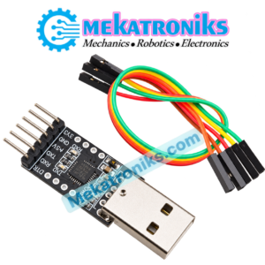
The CP2102 USB to TTL Module connects a computer’s USB interface to a compatible UART serial device. This six-pin converter supports serial communication, debugging, and programming of boards with a suitable UART bootloader. Confirm the header pinout, signal voltage, and target-board power requirements before connecting.
SKU: n/a - Buck/Boost Modules, Circuit Boards, Converters, Dc-Dc Converters, Dc-Dc Step Up, Power Bank, Power Modules & Batteries, Power Supplies
Wireless Charger Module PCB Circuit Board with Coil Charging 5W
 Buck/Boost Modules, Circuit Boards, Converters, Dc-Dc Converters, Dc-Dc Step Up, Power Bank, Power Modules & Batteries, Power Supplies
Wireless Charger Module PCB Circuit Board with Coil Charging 5W
About
- Wireless Charging Module,
- Universal 5W Plug and Play
- Dual USB Type C 3 Outputs
- Wireless Charger PCB Circuit Board Labor Saving
SKU: n/a


There are no reviews yet.