

No products in the basket.

Accessories, Arduino & Components
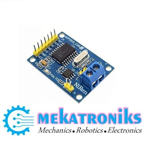
MCP2515 CAN Bus Module with TJA1050 Transceiver – SPI Interface
The MCP2515 CAN Bus Module combines an MCP2515 CAN controller with a TJA1050 transceiver. It connects a compatible microcontroller to a CAN network through an SPI interface. Use it for CAN communication experiments, embedded development, and student projects after checking the module’s voltage and oscillator specifications.
₨ 450
MCP2515 CAN Bus Module for Microcontroller Projects
The MCP2515 CAN Bus Module adds CAN communication to a compatible microcontroller through SPI. It combines a CAN controller and a transceiver on one board, providing the interface needed to exchange messages with a suitably configured CAN network.
For engineering students, hobbyists, and embedded developers in Pakistan, this module offers a practical platform for learning CAN messaging. Use it to build communication demonstrations and test compatible devices on a development bench.
MCP2515 Controller and TJA1050 Transceiver
The MCP2515 manages CAN message transmission and reception. Your microcontroller communicates with it through SPI to configure operation and exchange message data.
The TJA1050 connects the controller to the physical CAN bus through CANH and CANL. Together, these components support a CAN node when combined with suitable power, wiring, termination, and software.
Applications of the MCP2515 CAN Bus Module
- Arduino-based CAN communication experiments.
- Compatible 8051 microcontroller projects.
- Two-node CAN learning setups.
- Sensor data communication prototypes.
- Embedded system development.
- School and university engineering projects.
An 8051-based controller requires suitable SPI hardware or software implementation and a compatible driver. The module itself is a communication interface, rather than a microcontroller programmer.
Hardware and Voltage Compatibility
Check the complete module’s supply and signal voltage requirements before connecting it. Compatibility depends on the board design, not only the individual chip specifications.
For ESP32, Raspberry Pi, and other 3.3V controllers, verify the SPI signal levels carefully. Appropriate level shifting may be required if the module operates its controller at 5V.
Oscillator and Software Configuration
Identify the oscillator frequency printed on your module’s crystal. Configure your software to match that frequency and select the correct CAN bitrate.
Incorrect clock settings can prevent communication even when the wiring appears correct. Start with a basic test and verify message transmission before adding more complex functions.
CAN Network Wiring
Connect CANH and CANL to their matching network lines and provide the required ground reference. Use termination appropriate for the network layout; check whether your module already includes a termination resistor.
For initial testing, use a correctly configured second CAN node. Keep wiring organised and confirm that both nodes use matching communication settings.
Product Overview
| Specification | Details |
|---|---|
| Product type | CAN bus communication module |
| CAN controller | MCP2515 |
| CAN transceiver | TJA1050 |
| Microcontroller interface | SPI |
| Bus connections | CANH and CANL |
| Supply voltage | Confirm for the supplied board |
| Oscillator frequency | Check the fitted crystal |
Buy MCP2515 CAN Bus Module in Pakistan
Choose the MCP2515 CAN Bus Module from Mekatroniks for compatible embedded communication projects. Confirm the supply voltage, oscillator frequency, and termination arrangement before ordering.
Based on 0 reviews
Be the first to review “MCP2515 CAN Bus Module with TJA1050 Transceiver – SPI Interface”
Related products
- Arduino & Components, LCD, LCD Display & Lights, Sensors
IIC/I2C 16 Pin Serial Interface LCD Display Adapter Module
 Arduino & Components, LCD, LCD Display & Lights, Sensors
IIC/I2C 16 Pin Serial Interface LCD Display Adapter Module
About
- IC/I2C Serial Interface Adapter module.
- Or I2C interface module for 16×2 (1602) & 20×4 (2004).
- LCD displays with on-board contrast control adjustment.
- Backlight and I2C communication interface.
SKU: n/a


There are no reviews yet.